Description
>>>Manual: Click here to open<<<Description:
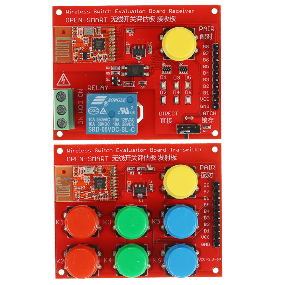
This evaluation board kit can be used to quickly evaluate and test the functions of the onboard wireless switch transmitter and receiver modules.The kit includes one pair of transmitter and receiver modules. And the frequency is 2.4GHz. There is the MCU on board with built-in encoding and decoding code, pairing code.When you do the remote control operation for the first time, you need to pair the transmitter and receiver, and you do not need to do it again in the future.It is easy to implement remote control without programming. It is very popular and easy for remote control systems, such as wireless doorbell, remote control rolling gates, smart car, smart home, etc.
Specification:
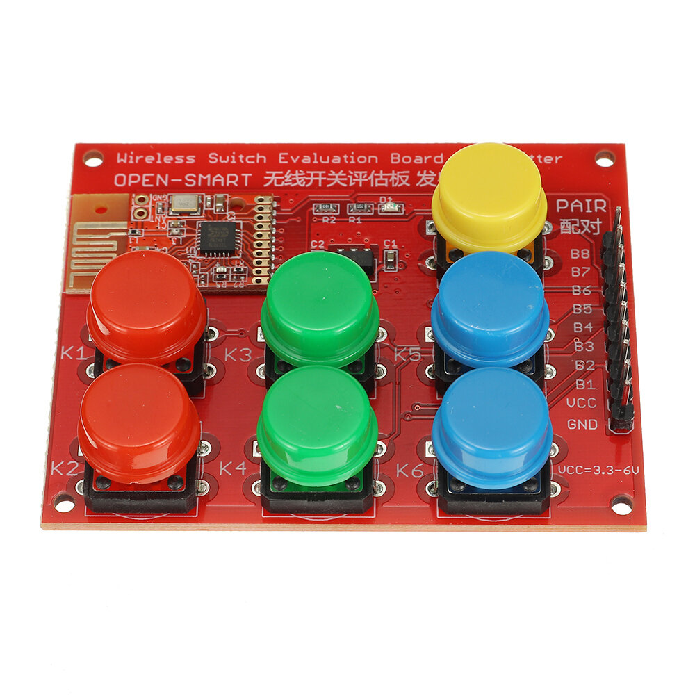
About Wireless Switch Evaluation Board Transmitter (will be abbreviated as TX module below):-Switch number of channels: 6 channels;-Input ports: 6-channel key input, active low;-Working voltage VCC pin: 3.1-5.3VDC;-Working Current: 0-25mA;-Working frequency: 2.4GHz;-MAX Transmission distance: 80 meters (open area);-D1 LED: Each time you press the button will light up a time;-PAIR button: yellow cap, for pairing;-K1-K6 buttons: Used to control 6 outputs of RX module, active low level;-B1-B8 pins: directly connected to the B1-B8 pins of the SMD module on the board;-Antenna: Built-in PCB antenna;
About Wireless Switch Evaluation Board Receiver (will be abbreviated as RX module below):-Switch number of channels: 6 channels;-Output port current: 5mA (max);-Output mode: LATCH mode or DIRECT mode;-Working voltage VCC pin: 3.1-5.3VDC (if the 5V relay on the board is not used), 4.8-5.3VDC (if the relay on the board is used);-Working frequency: 2.4GHz;-Working Current: 25mA;-Sensitivity: -85db;-PAIR button: yellow cap, for pairing;-Channel 1 output is connected to a 5V relay, which is isolated by optocoupler;-1-6 channels are connected to an output indicator;-Toggle switch on the board: used to switch the output mode, LATCH is the latch mode (only press the button to change the output level), DIRECT is direct mode (press the button light will be on, and release the button, the LED of RX module light goes off after 350 milliseconds);-D1-D6: Output LED, active high level output;-B1-B8 pins: directly connected to the B1-B8 pins of the SMD module on the board;-Antenna: Built-in PCB antenna;-Great for DIY;
Pairing Process:Step1: Power up for the two modules. Press and release the PAIR button of RX module, then D6 LED is on (tells it enters the pairing state). Press and release the PAIR button of TX module within 10 seconds, then the D6 LED flashes for a while and keep the light on.It is also possible to pairing this RX module with more TX modules (up to a total of 20).
Step2: Wait until D6 LED is off. You can press the K1~K6 button of TX module to test.You can push the toggle switch on RX module to learn the difference between LATCH and NON-LATCH output mode.NOTE: A transmitter module can be paired with multiple receiver modules, and one receiver module can only be paired with 20 transmitter modules.
Package included:
1 x Wireless Switch Evaluation Board Transmitter1 x Wireless Switch Evaluation Board Receiver

